
Maintaining life safety drawings
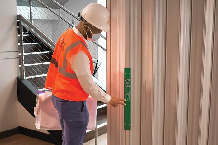
An engineer inspects the accordion fire door in accordance with the facility’s life safety plans.
Photo courtesy of TLC Engineering Solutions
The job of a health care facilities manager is multifaceted and complex. Renovation projects, environment of care rounds, mock surveys, local fire marshal visits, state department of health inspections and accreditation surveys are all realities of this position.
The success of any inspection can greatly depend on the accuracy of life safety drawings. They provide the roadmap for the life safety features of the building. At a minimum, they should include locations of all fire and smoke barriers, shafts, exit stairs, passageways, horizontal exits, suite boundaries, smoke compartments, hazardous areas, sprinkler protection and occupancy separations, such as for health care, ambulatory care and business.
When life safety drawings show a storage room as a hazardous area with a 1-hour fire barrier enclosure, the surveyor will expect to see a compliant 45-minute-rated door and walls that go to the structure with all penetrations properly sealed. If the drawings show a 2-hour rated fire barrier, the surveyor will expect to see a compliant 90-minute door and a fire damper. In areas not identified as suites, the surveyor will expect to see a clear 8-foot corridor, with the exception of permitted wheeled equipment.
This is why it is so important to keep the drawings updated and accurate.
Living documents
Life safety drawings are living documents that must be continually updated as areas change use, walls are moved, doors are installed or removed, or the facility is altered in other ways. Most people will update the drawings during an addition or renovation project; however, failing to keep the drawings updated with smaller changes can cause problems down the road.
An older common black-and-white version of a life safety symbol legend and a similar common-color version of a life safety symbol legend.
Graphics courtesy of TLC Engineering Solutions
Some facilities maintain their drawings with in-house staff, while other hospitals rely on outside consultants. It is best practice to have life safety drawings reviewed and updated on an annual or semiannual basis. Any changes in the interim can simply be identified with a note on the drawings indicating the change as well as the date of the change. (Drawings should be dated to reflect the last time they were reviewed or revised.)
Life safety drawings require a lot of information. However, overloading the drawings with too much information can make them difficult to read; balance is key, and different situations may require different information.
Drawings that are issued for a construction project may need to include more information than the set of documents used as a living life safety document. For instance, some state or local building or fire officials may want to see all fire alarm devices, exit signs or portable fire extinguishers shown on the life safety plans; but, depending on the size and scale of the drawings, these items may start to obscure the necessary information.
Likewise, for a construction or renovation project, it is typical to show travel distances to exits, smoke barriers or suites. However, because these dimensions don’t change once the walls and doors are in place, it is not necessary keep this information on the drawings.
As the field continues to evolve, health facilities professionals are seeing some simple and practical changes that address accuracy. Prior to the last decade, life safety drawings were printed as blueprints or black-and-white plots. Line types in the past were often a series of dots and dashes to differentiate between hourly ratings and whether the wall was for smoke or fire.
Color drawings have now become common, greatly improving the legibility of the drawings and reducing the likelihood of errors. Other items that have helped improve readability are line styles, shading of suites, identification of hazardous areas using specific patterns and clearly identifying the smoke compartments.
Standard requirements
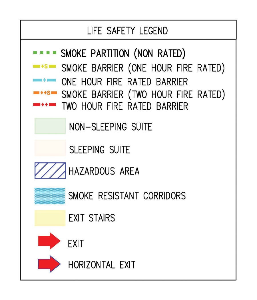
The National Fire Protection Association’s NFPA 170, Standard for Fire Safety and Emergency Symbols, offers a national standard for architectural symbols and includes the line types for the list of fire and smoke barriers.
A life safety symbol legend using the NFPA 170 national standard for architectural symbols.
Graphics courtesy of TLC Engineering Solutions
Smoke compartments are delineated by smoke barriers; however, these compartments sometimes are difficult to discern, and the inclusion of a smoke compartment key plan can help to clarify. This can also provide an overall picture of the larger and smaller compartments when planning emergency evacuation procedures. Another good idea is to list the smoke compartments with the associated area of each corresponding smoke compartment.
An overall life safety plan for each floor is imperative to see the big picture. For some facilities, the entire floor will fit on a single sheet at a legible scale. Larger facilities often will need to break up the floor plan onto multiple sheets with match lines to show the information at a legible scale. Either way, it is good to have an overall floor plan, with a key, to show how the building is broken into the different sheets.
Suites are necessary when spaces are used to treat patients without separation from the circulation space (e.g., only a curtain separation such as a post-anesthesia care unit). Other times, the arrangement of the space may not require the area to be treated as a suite, but it may be advantageous to make the area a suite based on the usage of the space and whether or not it complies with all of the suite requirements. This is often the case with an emergency department or an operating suite where corridor clutter becomes difficult to manage.
Hazardous areas must be identified on the life safety drawings. These areas may include storage rooms of certain sizes, soiled holding rooms, boiler rooms, central bulk laundry or physical plant maintenance shops (NFPA Table 18/19.3.2.1 lists the specific areas that are classified as hazardous). In most cases, the hazardous areas in Chapter 18 are enclosed with 1-hour fire barriers and sprinkler protected (sprinklers are required for all new health care occupancies). These same areas in Chapter 19 generally are enclosed with a 1-hour barrier or sprinkler protected and enclosed with a smoke partition/self-closing, positive-latching door.
Storage space in hospitals is always at a premium, and there never seems to be enough space for everything. It is not unusual for a team conducting an environment of care round to find that what was once an office is now being used for storage. Under Chapter 43 of NFPA 101®, Life Safety Code®, this would be a change of use in an existing health care facility and would be permitted as long as the area of the room does not exceed 250 square feet, is protected throughout by automatic sprinklers, and enclosed with a smoke partition and self-closing, positive-latching door. This is a valuable compliance approach to use for areas that have been converted to storage and do not comply with the requirements for new construction.
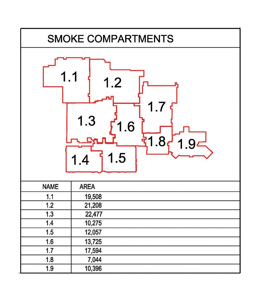
A smoke compartment key plan can help to clarify smoke compartments and smoke barriers
Graphics courtesy of TLC Engineering SolutionsCredit goes here
Corridor walls often are a source of confusion because the term used in the Life Safety Code is not defined and the term used in the International Building Code (IBC) has special exemptions for I-2 occupancies. The Life Safety Code requires corridor walls (in fully sprinkler-protected buildings) to be constructed to “form a barrier to limit the transfer of smoke.” The IBC requires corridor walls to be “smoke partitions” but then adds an exception for corridor doors that states “shall not be required to be equipped with self-closing or automatic-closing devices, but shall provide an effective barrier to limit the transfer of smoke and shall be equipped with positive latching.”
The requirements in the two codes present conflicting requirements. The Life Safety Code allows corridor walls to terminate at the ceiling as long the ceiling is “constructed to limit the transfer of smoke.” The question becomes, what should be the designation of these walls on the life safety drawings? To further complicate the issue, the Life Safety Code requires certain hazardous areas that are sprinklered (storage rooms less than 100 square feet but more than 50 square feet in new construction) to be constructed with smoke partitions. The answer is not simple.
The plans for a construction or renovation project must be submitted to the authority having jurisdiction (AHJ) for review of both the building code and the Life Safety Code, so it must include the information for both codes as well as any additional information (e.g., exit signs and fire alarm devices) required by the applicable AHJ. This set of living life safety documents is used for continued compliance with the Life Safety Code as opposed to the plans submitted for compliance with the building code at the time of construction. Because most surveyors are inspecting the facility for compliance with the Life Safety Code, the terminology from the Life Safety Code should be used for the living life safety drawings.
Many hospitals today are protected throughout by automatic sprinkler protection in accordance with NFPA 13, Standard for the Installation of Sprinkler Systems. However, there are a number of hospitals that are only partially sprinklered and are working toward being fully sprinklered as renovations occur. In these partially sprinklered facilities, it is essential to identify which areas are not yet sprinklered; this is usually done by using a defined pattern over those areas. Unfortunately, these patterns on top of other patterns can make the drawing more confusing. Coordination of the different patterns should be planned to allow for clarity.
Code consultants assessing a facility often will recommend decommissioning rated fire barriers or smoke barriers. While this may be an option, in many cases, care must be exercised before decommissioning any fire protection features. (The American Society for Health Care Engineering (ASHE) has developed a Life Safety Decommissioning Tool, which can be accessed by ASHE members at ashe.org/decommissioning).
A smoke compartment key plan can help to clarify smoke compartments and smoke barriers.
Graphics courtesy of TLC Engineering Solutions
The Life Safety Code states that “No existing life safety feature shall be removed or reduced where such feature is a requirement for new construction.” For example, a 300-square-foot storage room constructed as a hazardous area with a 1-hour fire barrier enclosure and sprinkler protection that was built in 2004 is now considered existing and would be subject to the requirements of Chapter 19. Under Chapter 19, this room would only require a smoke partition because it is fully sprinklered. However, because this room was already constructed with a 1-hour fire barrier enclosure, the rated enclosure must be maintained because that is what is required for new construction.
There are occasions when smaller smoke compartments can be combined to reduce the amount of smoke barrier walls that need to be maintained and smoke detection at smoke barrier doors that can be eliminated. Again, care should be exercised to ensure that all the requirements of the combined smoke compartment comply with the requirements under Chapter 18 and that there are no special conditions that will be affected by combining the smoke compartments (e.g., conditions of an approved waiver). In addition, the fire response procedures need to be reviewed and updated to verify they have been coordinated with the revised smoke compartment layout.
Life safety drawings can be a useful tool in evaluating where special locking arrangements can be used. Depending on whether the facility is using the special needs locking arrangement from NFPA 18/19.2.2.2.5, delayed egress or access control, the life safety drawings can help determine compliance with all of the provisions. Because locking doors have become so common, some facilities have started to denote the locking arrangements on the life safety drawings using different symbols for different locking types. This is not required, but in some cases can be helpful to understand exiting from the facility.
Because many hospitals today are designating portions of the facility as “ambulatory health care occupancy,” “business occupancy” or even “factory/industrial occupancy” (in the case of the central energy plant), it is necessary to identify these occupancies on the life safety drawings and to show the required occupancy fire separations. Again, a small key plan located on the drawings indicating the different occupancies can provide clarity.
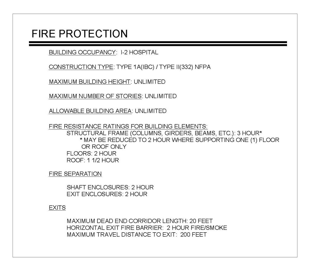
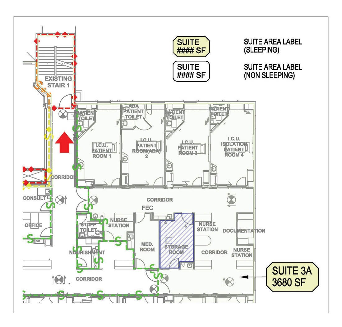
Although not required or commonly shown, a code summary can add value to living life safety documents.
Graphics courtesy of TLC Engineering Solutions
Although not required or commonly shown, there are a few more items that can add value to living life safety documents. For instance, the building construction type should be noted on the drawings. Because a minimum building construction type is a requirement of the Life Safety Code, it is important to document this information to show compliance. This also will assist in future projects when building additions or major renovations are desired. It also documents where previously approved waivers or special conditions approved by applicable AHJs have been granted.
Living documents
The necessity of having a living life safety document cannot be overstated by health facilities professionals.
While navigating through seemingly near-constant adjustments can feel precarious, and at times overwhelming, due diligence in mitigating mistakes and oversights is imperative.
As the field and all of its moving parts continue to evolve, being equipped to swiftly and sufficiently address changes as they occur will keep these living documents alive and well.
James Peterkin, PE, LEED AP, SASHE, is principal, senior fire protection engineer and code consultant at TLC Engineering Solutions, based in Orlando, Fla. He can be contacted at jim.peterkin@tlc-eng.com.
Related Articles

ASHE launches committee to help answer member questions
The new MyASHE Response Committee will work in coordination with the ASHE Regulatory Affairs Team to monitor and respond to critical questions in the MyASHE online community.

What to expect at the 2026 Health Care Facilities Innovation Conference
Taking place Aug. 2-5 in Minneapolis, the conference features tailored tracks to align with distinct knowledge levels and career stages.

Build a ‘see something, say something’ safety culture
From risk assessments to rounding, several free and easy-to-use tools will help keep healthcare environments and occupants safe.