
Predictive maintenance for hospital equipment
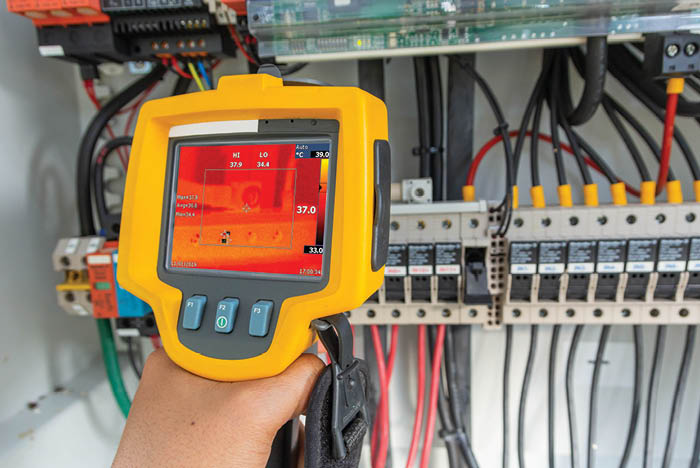
Infrared thermography is a common method for nondestructive testing of electrical equipment.
Image by Getty Images
Predictive maintenance (PdM), also known as condition-based maintenance (CBM), can improve the reliability of health care infrastructure equipment and systems, while also reducing maintenance costs.
In fact, PdM or CBM can help health facilities professionals solve problems they may not even know exist.
Although PdM is only one element of an overall reliability-centered maintenance (RCM) program, it is a very important tool in the RCM toolbox and a very useful supporter of RCM decisions.
PdM and RCM
When discussing PdM, one first needs to consider its place within an overall RCM program. RCM was discussed in an article by Rick Joslin on Health Facilities Management’s website entitled “A journey toward reliability-centered maintenance,” which was one of a series of reliability asset management articles (see the resource box on page 40 for more).
In the article, Joslin describes RCM as a strategy that “requires the organization to think through all aspects of an asset’s existence — from what it is supposed to do, to how it is supposed to do it, how it can fail (including hidden ways), what is affected by a failure and what could be done to prevent failures.”
Click image to enlarge and read caption
As just one element within an overall RCM program, PdM can be a very useful process to assist health care facilities in identifying potential future failures in time to avoid the consequences of those failures, and thus preserve the functions of the assets as well as the systems those assets serve.
Many health care facilities currently have ongoing preventive maintenance (PM) programs that consist of lists of activities (often called PMs) to be performed at calendar-based intervals. Sometimes those PMs are based upon past practices, and sometimes they are based upon the original equipment manufacturer (OEM) recommendations.
CMS Tag A-0724 — “Facilities, supplies, and equipment must be maintained to ensure an acceptable level of safety and quality,” requires facilities to inspect, test and maintain all equipment to ensure they are safe, available and reliable. This requires that the organizations subject to Medicare and Medicaid requirements be able to prove compliance with the following hierarchy of inspection, testing and maintenance requirements, including:
- Law and regulation.
- OEM recommendations for both activities and related frequencies — if the organization does not have a Centers for Medicare & Medicaid Services (CMS)-compliant alternative equipment maintenance (AEM) program in effect.
- Requirements of a Tag A-0724-compliant AEM program.
While many health care organizations believe their existing historical PM processes to be compliant with OEM recommendations, some may not be able to prove their compliance during accreditation surveys. This is because the processes (activities and related frequencies) and written PMs in many cases were established long before CMS updated Tag A-0724 on Dec. 20, 2013, or even its Dec. 2, 2011, predecessor Survey and Certification letter 12-07-Hospital — Clarification of Hospital Equipment Maintenance Requirements.
The 2014 American Society for Health Care Engineering (ASHE) book entitled Maintenance Management for Health Care Facilities is referenced by CMS Tag A-0724 as an acceptable source of guidance for AEM Program decisions.
Click image to enlarge and read caption
The ASHE book preface states, “Besides preventive maintenance there are alternative approaches such as reliability-centered maintenance, predictive maintenance and conditional maintenance.” Appendix D, entitled “Conditioned monitoring/predictive maintenance,” includes discussions of techniques such as infrared thermography, ultrasound testing, vibration analysis and oil analysis.
In-person options
Many health care organizations have for years authorized regular in-person inspections using non-destructive testing (NDT) of physical environment equipment. Two simple examples are generator fuel oil testing and medium-voltage transformer oil testing.
The annual generator fuel-oil test is code-mandated, and the transformer oil test is generally governed by OEM recommendations; the National Fire Protection Association’s NFPA 70B, Recommended Practice for Electrical Equipment Maintenance; or the American National Standards Institute/InterNational Electrical Testing Association’s Maintenance Testing Specifications for Electrical Power Equipment & Systems.
Resources
The in-person PdM inspection and testing approach has historically relied upon scheduled PdM inspection and testing activities by personnel, depending upon the time frame, which are intended to provide sufficient time for planning an outage and performing maintenance activities to prevent the future failure before that failure occurs. The key is that the scheduled inspection and testing activities must occur sufficiently in advance of any potential failure to allow the corrective action time necessary to avoid that future failure.
Another simple example of an in-person process versus a permanently installed process is the code-based requirement regarding testing of line isolation monitors (LIMs), which are used in isolation power systems that serve operating rooms.
These devices are required by code to be tested at least monthly by actuating the LIM test switch in accordance with NFPA 99-2012, section 6.3.2.6.3.6. However, for LIM circuits with automated self-testing, a manual test is only required annually. A monthly manual in-person requirement becomes an automated process, plus an annual in-person requirement with presumably no adverse impact on equipment performance or patient safety.
- Infrared thermography (sometimes called “infrared scanning”). Some common historical uses of such NDT in health care organizations have been infrared thermography testing of electrical equipment (such as transformers, switchgear, switchboards, panelboards, transfer switches, generators, cables and wiring connections); mechanical equipment (such as rotating equipment, bearings, steam traps, ducts and piping); and outer surfaces of buildings, commonly known as building envelopes.
The results of those scheduled infrared thermography inspections may identify indicators of potential future equipment failures. These indicators, when acted upon in a timely manner, can provide opportunities to avoid potential failures before any related damage or other adverse consequence occurs.
- Ultrasonic condition monitoring. Another example of NDT is ultrasonic condition monitoring, which is not a new technology. Ultrasonic sounds are usually received through the air and through solid surfaces. Pressurized system leaks can be detected with an ultrasonic acoustic scanning device. Ultrasound technology is also used to detect structure-borne situations, such as those generated by bearings or by leaky valves.
Mechanical defects in rotating machinery, including out-of-balance conditions, a bearing about to seize, or other types of vibration or misalignment may be detected with ultrasonic acoustic monitoring or other types of vibration analyzers. The collection and analysis of vibration data associated with rotating machinery is also used to detect component defects and allow mitigation of pending rotating machinery failure for generators, motors, fans, air-handling units and other equipment.
Additionally, gas and liquid leakage can produce a broad range of sounds that can be picked up by ultrasonic monitoring. As subtle changes begin to occur in mechanical equipment, the directional nature of ultrasound allows these potential warning signals to be detected early before an actual failure.
However, mechanical equipment is not the only equipment that can benefit from ultrasonic monitoring. As an example, hand-carried ultrasound monitoring equipment has been used for several decades as a process to detect potential failures in medium-voltage electrical equipment. Electrical emissions such as arcing, tracking or corona also produce a broad range of sounds. With effective monitoring equipment, the ultrasonic components of these sounds are usually directional and localized, making it easy to isolate these signals and detect their sources.
- Partial discharge (PD) monitoring. PD monitoring, also sometimes called “electrical discharge testing” or “corona testing,” is another very useful process for assessing the condition of electrical systems, and even electrical motors. The PD, acting as a small spark inside or on the surface of electrical insulation, is a leading indicator of a potential insulation problem. PD activity that accelerates quickly can result in complete insulation failure. PD can happen in air gaps, voids, cavities, spacers, supports, gaps inside conductor insulation and other locations.
Most PD monitoring in health care facilities is presently used during scheduled inspection and testing activities. Although periodic in-person inspection and testing PD surveys can provide important results, the benefits of installed PD monitoring systems can provide more effective results.
Installed PD monitoring equipment is often more sensitive than portable PD equipment, and it also checks and reports the health of the monitored equipment. Because PD measurements are based on both power system operating conditions and related equipment environment, an online system is likely to provide more reliable results than an offline system.
PD analyses can detect many pending issues within electrical switchgear, including discharges in air gaps, surface tracking, sparks within insulation voids, insulation problems in cable terminations, insulation problems in connected equipment, poor electrical connections, defects in potential transformers or current transformers, and problems with incoming bus ducts (busway sections).
Equipment failure
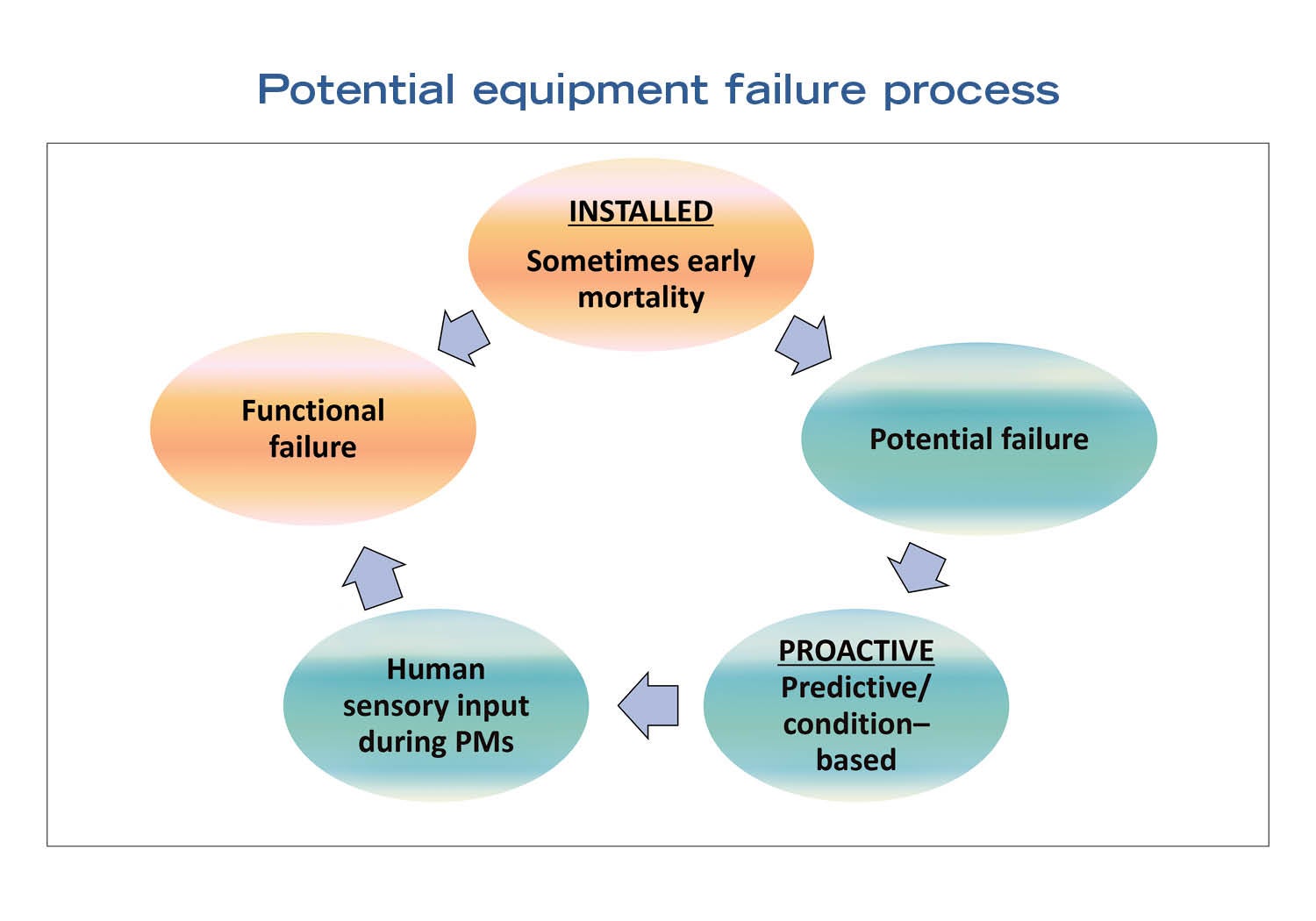
The simplest visual approach is often known as the P-F curve, where P represents a point where “potential failure” can occur (meaning that the failure process may commence anytime but has not concluded), and F represents the point where the equipment in question has “functionally failed” (meaning it’s too late).
There have been numerous studies, publications and graphics of equipment failure patterns and the related individual versions of P-F curves. An internet search can provide easy access to those sources.
Most P-F curves differ from each other. However, there tends to be some degree of similarities among many of the variations. For example, the equipment condition is usually at its highest at the start of the curve and equipment condition is as high as it is likely to be. (Sometimes issues arise right after installation or right after repairs, and sometimes they do not.)
Then, after some period, the potential failure may occur. This means that the failure process may be initiated before long. Some things are just unpredictable, and that is why facilities professionals measure and probe with the technical resources of the PdM devices.
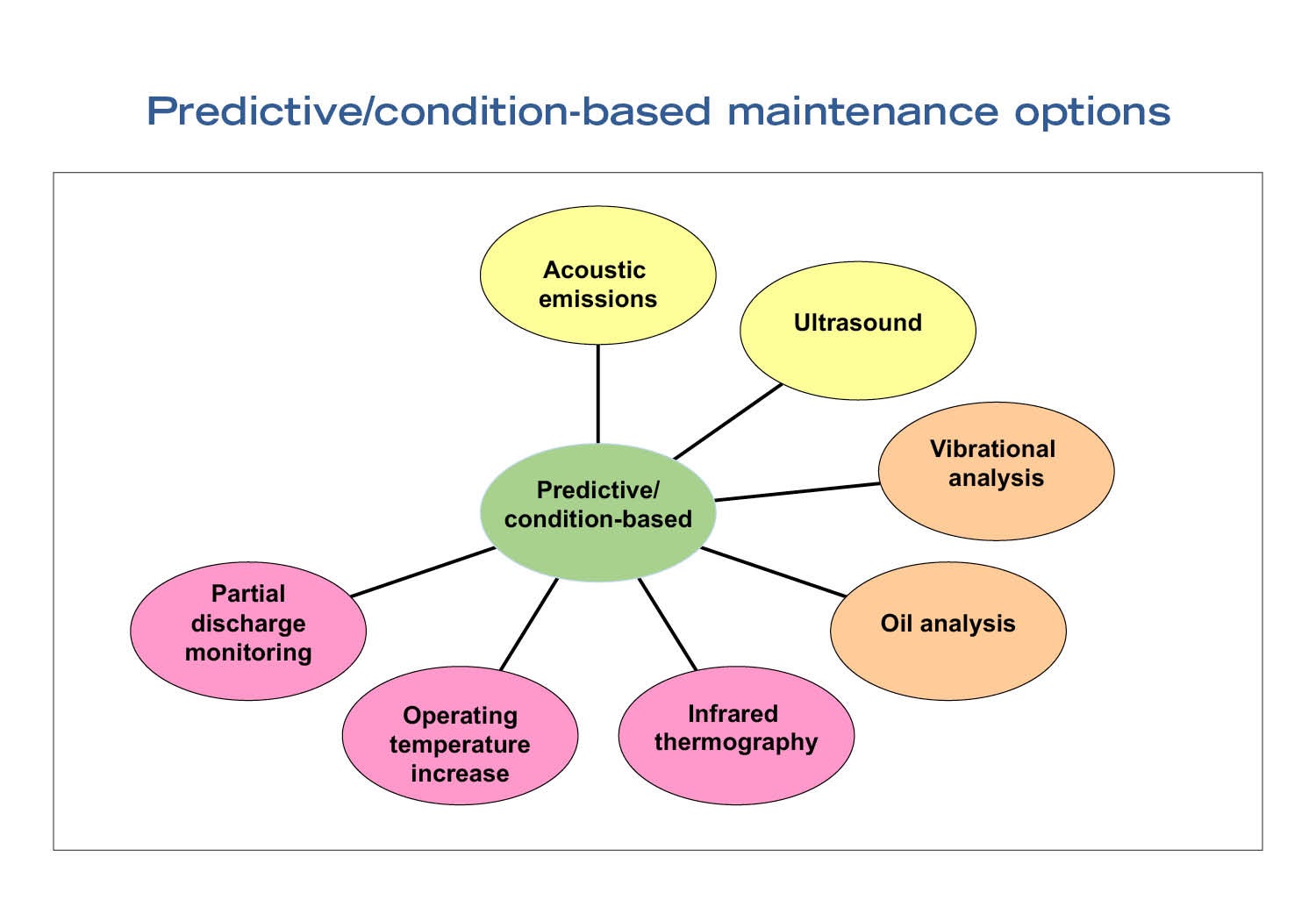
Next is what some might call a predictive portion of the P-F curve. The potential failure may have occurred, but it may not be known yet, unless the facilities professional has been probing effectively. One or more of the following tools may catch it, depending upon the technology being used and the choices in applying options such as acoustic emissions and ultrasound (previously discussed), vibration analysis (changes in vibration), oil analysis (wear debris in oil), infrared thermography, operating temperature increase and partial discharge monitoring.
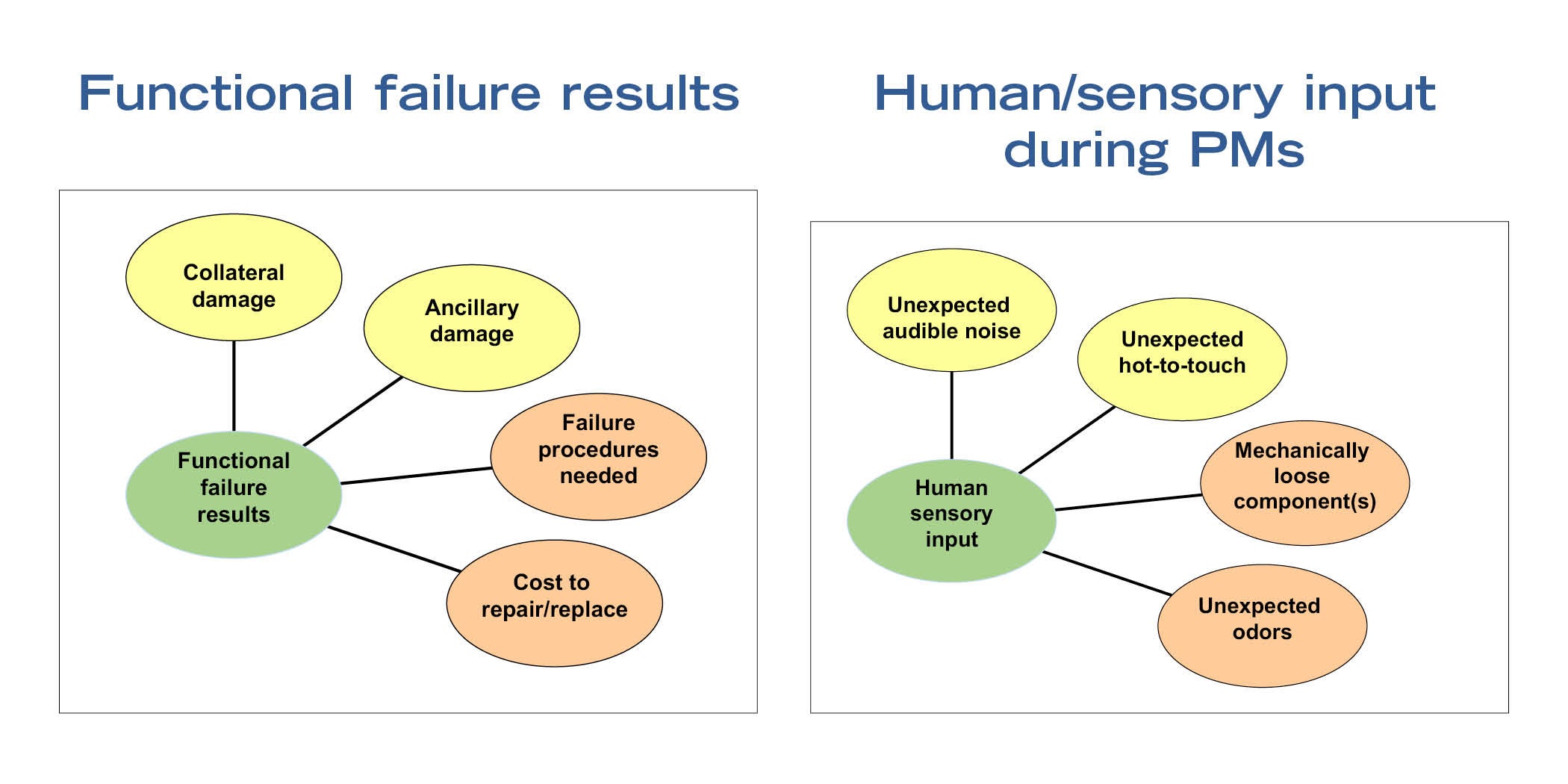
After that, in the absence of PdM equipment and processes (either manually operated or permanently mounted and functioning), facilities professionals may have scheduled some PM in a timely manner and are able to determine the following through human sensory input, even though the equipment still appears to be functioning to some degree: (1) there is audible noise coming from the equipment that should not be there; (2) the equipment is hot to the touch and hotter than previously experienced; (3) some portion of the equipment is mechanically loose; (4) something smells wrong in the equipment space; and (5) anything else that doesn’t seem right.
Click image to enlarge and read caption.
And, finally, there is the equipment functional failure zone. There may also be collateral damage and/or ancillary damage. Facilities professionals should make sure their mandatory equipment failure procedure is effective, applies to the failed component(s) and is accurate and up to date because it is then too late to create one. The repair and replacement cost is probably also at its peak, with no time to negotiate costs or schedules.
Consider the options
Facilities professionals must consider their available PdM options and assign the options (either in-person applications or permanently installed applications) that best support their RCM decisions for each asset to which they plan to assign PdM.
Understanding the most likely failure modes for the equipment under consideration for PdM should be an important factor in PdM choices. If facilities professionals want to start with their utility equipment inventory, they should make sure it is up to date and accurate first.
Additionally, they should consider carefully what technologies they will use and where. Different systems and equipment may have very different failure modes, and technology choices could be quite important.
Finally, facilities professionals should take advantage of the options already in place – they may already have a portion of a robust in-person PdM process for some important equipment or systems.
Additional maintenance issues that can benefit from PdM
Beyond the examples discussed in the main article are many other unexpected health care facilities maintenance issues that can be remedied by using predictive maintenance (PdM) techniques. They include the following:
- Electrical signature analysis (ESA) for motors. ESA uses both historical and newly considered inputs. These inputs include machinery (vibration) analysis, spectrum analysis of the frequency content of a time domain signal, and frequency analysis of time waveforms. ESA uses a motor’s supply voltage and operating current to identify existing and developing faults in the entire motor system. These measurements act as transducers and any disruptions in the motor system cause the motor supply current to vary (or modulate).
- In-person PdM inspection and testing of variable frequency drive (VFD) bus capacitors. VFD bus capacitors have a limited life span. They can and sometimes do fail within the expected service life rating. The expected service life rating only can be used as a general guideline because of conditions that can reduce the capacitors’ actual life span below the service life rating. Overtemperature, overvoltage, overcurrent, improper mounting or clamping, terminal connections, electromechanical wear and shelf life all are conditions that can reduce the limited life span of VFD bus capacitors that age faster than dry components. Overtemperature alone dramatically decreases the life span of the bus capacitors.
- In-person PdM inspection and testing of uninterruptible power supply (UPS) capacitors. Capacitors and batteries are the UPS components considered most prone to failure. Capacitors age over time, thus reducing performance. Excessive heat or current can speed up deterioration. Some capacitors are rated to deliver up to 10 years of service life with favorable operating conditions. Apparently, it is not uncommon to replace capacitors between four and eight years to reduce failure risk.
Common capacitor failure modes are reported to be excessive current, overuse (also called overwork) and/or excessive heat. Recommended routine in-person PdM inspection and testing includes inspections for oil leakage, deformation, scorched wires connected to the capacitor, burnt valve cap protrusion, small (or greater) increase in capacitor temperature and capacitance. The PdM activities include visual inspection, thermal imaging and use of a capacitance meter.
David L. Stymiest, PE, CHFM, CHSP, FASHE, is a senior consultant at Smith Seckman Reid, Nashville, Tenn. He can be reached at dstymiest@ssr-inc.com.
Related Articles

NFPA weekly update: July 6-10
NFPA releases the voting results from its Technical Meeting on certified amending motions proposed for the Life Safety Code and Health Care Facilities Code.
NFPA weekly update: June 29-July 3
NFPA shares voting results from its 2026 Technical Meeting and issues an errata regarding sprinkler protection of Class II and Class III liquids.
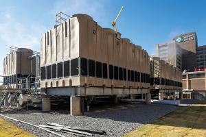
New cooling towers boost efficiency
Baptist Health Medical Center-Little Rock achieved significant reductions in energy consumption by upgrading its HVAC system.