
Time for a power system reliability check

Reliable health care facility power system equipment should have regular attention such as inspections, testing and maintenance.
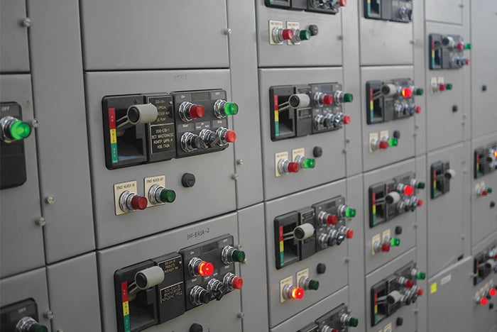
Image by Shutterstock
The reliability of a hospital’s normal power system depends upon many factors, including the system’s physical equipment and their arrangement, and facility professionals’ knowledge, training and informational tools.
In hospital and other health care facility electrical power systems, much of the operational focus has been on the emergency power systems. This is understandable, but normal power systems also require attention.
In many ways, a hospital’s normal power system is its first line of defense against power failures. Moreover, if an emergency power system’s scope is limited, the failure of normal power equipment can cause an adverse impact greater than expected.
Facilitating reliability
There are numerous ways to facilitate reliable and dependable normal power systems in health care facilities. These efforts start with power system planning and design, move into commissioning and documentation, and conclude with regular inspections and maintenance. Key areas of this progression include:
Planning for operational flexibility. The facility’s personnel will be responding to failures, whether external or internal. According to a Winter 2014 Inside ASHE article, an American Society for Health Care Engineering (ASHE) member survey “found that, on average, health care facilities experience about one utility outage per year.”
External failures of that nature could be the outage of the local utility grid or simply an outage of just one of multiple incoming utility circuits. Conversely, an internal failure could be a failure that disables a building main normal power switchboard, a power riser in a high-rise building, a motor control center or a distribution panel. In such cases, flexibility and the ability to understand the problem can be quite important in determining the necessary immediate response.
Dual utility circuits to a facility can mitigate the failure of one utility circuit. However, in smaller facilities, those two utility circuits may both connect through local switching to the same utility transformer. Or even with two utility transformers, the two transformer output feeders may terminate at different points on the same main switchboard distribution bus.
In its simplest terms, the use of redundant equipment such as two transformers, two separate main switchboards or two distribution panels is often referred to as an N+1 configuration, where N equals the required quantity needed to provide enough power to the loads.
However, this simple description ignores an equally important distinction: the difference between N+1 capacity and N+1 distribution. Two transformers provided to serve equipment that only needs one of them to operate can provide N+1 capacity. If either transformer fails, the other transformer can continue to carry the load. However, if both transformers are powered by the same feeder or even by the same switchboard, the loss of that feeder or switchboard will result in both transformers being out of service. This would be a case of N+1 capacity hampered by only N distribution to those transformers.
Adverse occurrences are not limited to problems with switchboards or panelboards. Dripping water and rising water are problematic with electrical equipment, electrical distribution pathways and even control wiring.
For example, sometimes water from a sprinkler or other flood source on an upper floor can find its way into an electrical closet and from there into a busway riser penetrating the floor. And sometimes that water can cause a short circuit, which is also called an electrical fault, within the busway riser. In this case, all equipment powered by the distribution pathway, which is also called the busway, will lose power. That will be the limit of the immediate exposure provided that the source equipment, whether a circuit breaker or fused disconnect switch, is selectively coordinated with the upstream equipment.
If the selective coordination between the busway riser source and the upstream equipment is not correct because of changes or lack of maintenance, an entire distribution panel or switchboard could also fail because of a simple water discharge issue or other short circuit caused elsewhere within the facility. Because health care facilities typically have a large number of changes, periodically revisiting and updating prior short circuit analyses and time-current coordination studies is recommended. Ineffective selective coordination due to changes or the lack of maintenance can result in small problems becoming much larger problems.
The latest edition of ASHE’s updated Electrical Systems Handbook for Health Care Facilities specifically addresses the topic of selective coordination in a new chapter.
Designing for expandability. The high rate of change in technologies and other clinical practices drives almost constant change for health care power infrastructure. Systems and equipment that include features to adapt to changing future needs are more likely to allow expansion without adversely affecting reliability.
Existing electrical power equipment may have features that facilitate load growth. Examples include switchgear bussing capable of accepting more load, compartments capable of accepting breakers in the future and spare breakers without immediate load assignments to them, among others. These features can result in power system evolution within the original concepts, enabling a future that can be more easily understood and managed.
Creating physical separation. Power system elements that are intended to be backups to one another are sometimes placed in close proximity to each other because of budget constraints. An example could be switchboard A and switchboard B located near each other within the same room. Physical conditions such as flooding or damage from an arc flash could adversely affect both pieces of equipment. If the budget permits, health facility professionals also should consider separating the distribution pathways, also called the feeders, supporting both pieces of redundant equipment.
Commissioning. Sometime after a new building is occupied or a power system upgrade has been in operation, facility professionals can be dismayed to find that their new normal power equipment doesn’t work the way they intended. If faults or overloads were to occur at a later date, facility professionals would be dismayed if they discovered that the electrical protective coordination didn’t work as intended to mitigate the impact of the adverse condition. These and other problems can be avoided if the installation is verified by a thorough commissioning process.
The commissioning process confirms the work as it is installed and monitors the startup planning and execution. The prefunctional checklists can include verification of every attribute of every component and may be voluminous. Detailed step-by-step functional performance test scripts for large normal power systems can be more than 30 pages long. No equipment or operational detail is too small to be verified; future failures can often be traced to small errors or omissions, including small parts that were incorrect. Not verifying the correct protective coordination settings could cause larger outages than necessary if future short circuits and overloads were to occur. Programming errors have resulted in incorrect operation under some scenarios.
Providing clear information. Hospital power systems are often complex. Accurate main one-line diagrams that are regularly updated can be useful tools for performing day-to-day maintenance and especially when things go wrong within the power system. This information can be even more useful when it is contained within an online power monitoring system. Modern power monitoring and control systems also can contain features for controlling the equipment as well as monitoring equipment condition, advising of predictive maintenance needs and logging maintenance activities.
If a facility professional has not been able to document the myriad changes over an extended period, it may be necessary to audit elements of the existing electrical infrastructure. This can improve reliability by identifying common-mode failure potential, other weaknesses and areas for improvement.
Consistent equipment-naming conventions can be useful for facilitating speedy response to power failures within larger facilities. Clear and consistent labeling on a panel or switchboard may include the power source to that equipment, other equipment supplied by that panel or switchboard, and other information as needed by the facility personnel. If equipment numbering changes over time, it is important to be very clear about the legacy equipment identifier versus the updated equipment identifier if a decision is made to allow the legacy identifier to stay on the equipment.
Complex equipment requires more attention to operational clarity. In larger buildings, the main switchgear layout may be complex and not easily understandable to the night, weekend or holiday staff member who is charged with diagnosing the problem and getting the power system back online as soon as possible. With complex equipment, a mimic bus, which is a graphic representation of the equipment’s internal current flow, can assist staff members in determining response actions. Proper and thorough labeling of all components of the electrical system will also be a great assistance to any staff member required to perform work on the electrical system.
A clear utility failure procedure that considers equipment-specific operation such as where to go and what switches to operate also will support correct responses if complex equipment is affected during an adverse event.
Conducting regular inspections. There is no code requirement to perform weekly inspections of normal power systems similar to the National Fire Protection Association’s NFPA 110, Standard for Emergency and Standby Power Systems, requirement for weekly inspections of emergency power supply systems. However, the potential value of regular inspections finding a problem before it creates a failure can be huge.
What should be included in a regular inspection of a major switchgear room or even a smaller electrical room? Facility professionals can consider the following things when they enter an electrical power equipment room:
• Sight. Observations can focus on pilot lights, panels and meters; evidence of combustible storage, which is a fire risk; and evidence of water ingress from above, below or from nearby rooms. Also, facility professionals can look at adjacent rooms to determine if there are any potential problems that might adversely affect the electrical power system equipment.
• Smell. Energized electrical equipment sometimes warns of upcoming faults with a distinctive odor, such as burning or any other unusual smell.
• Sound. Electrical equipment sometimes warns of loose components by changing or amplifying its usual sounds.
Facilitating maintenance. Predictive maintenance (PdM) is commonly considered to be the process of assessing operating equipment condition to determine when maintenance should be performed before failures occur. Predictive maintenance often results in cost savings over purely calendar-based preventive maintenance.
One common PdM approach is annual or other regular thermographic, or infrared, scanning of internal portions of operating electrical power equipment. Devices called infrared viewports are often provided to permit the scanning equipment to assess the temperature of interior parts within the electrical equipment without the need to open the equipment while it is energized. New equipment can be specified with these viewports, and existing equipment can be retrofitted with viewports by the manufacturer while the equipment is offline for modification, scheduled maintenance or other reasons.
Using these infrared viewports for thermographic scanning relates to another activity pertaining to operational reliability: the electrical safety program. It can be very dangerous to perform work within energized electrical equipment. An arc flash caused by performing such work has been known to cause unexpected equipment failure and severe personnel injury and even death.
Other PdM tools besides thermographic scanning include equipment and systems to monitor medium-voltage insulation within equipment and cables, along with internal temperature monitoring systems within the equipment.
Electrical power maintenance resources, including NFPA 70B, Recommended Practice for Electrical Equipment Maintenance, equipment manufacturers’ publications and publications from other organizations such as the InterNational Electrical Testing Association are available and should be consulted when establishing power system inspection, testing and maintenance programs. For more detailed information on hospital electrical equipment maintenance, refer to the August 2014 Health Facilities Management article titled “Maintaining Power Systems.”
Another feature that facilitates maintenance is operational flexibility. Flexibility can be achieved with multiple items of equipment, such as a switchboard A and a switchboard B. Another example is with a double-ended unit substation with a main-tie-main breaker arrangement. This allows for planned equipment outages, or shutdowns, for maintenance and can also facilitate emergency response to internal equipment or distribution failures. ASHE’s Electrical Systems Handbook for Health Care Facilities contains examples of flexible power system design features with their pros and cons.
Older equipment can also be reconditioned or upgraded to extend its useful life. This may allow the organization to take advantage of technological improvements, which can bring added reliability benefits.
First line of defense
The reliability of normal power systems is the first line of defense in preventing power outages. Thorough preparation and execution throughout system planning, design, construction and maintenance will help ensure that emergency systems will only be used under the most extreme circumstances.
David L. Stymiest, PE, CHFM, CHSP, FASHE, is a senior consultant at Smith Seckman Reid Inc., Nashville, Tenn. He can be reached at DStymiest@SSR-Inc.com.
Related Articles
NFPA weekly update: June 29-July 3
NFPA shares voting results from its 2026 Technical Meeting and issues an errata regarding sprinkler protection of Class II and Class III liquids.
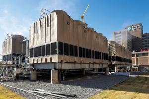
New cooling towers boost efficiency
Baptist Health Medical Center-Little Rock achieved significant reductions in energy consumption by upgrading its HVAC system.
ASHE task group tackles battery safety in health care
The Battery Safety Task Group is conducting research and surveys to understand and develop practical guidance on the facilities risks associated with battery technologies.