
Resilient design strategies to withstand extreme weather events
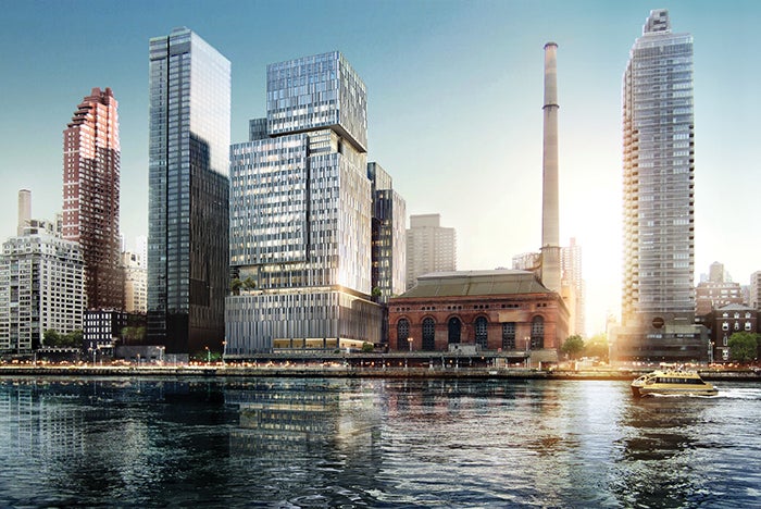
The Memorial Sloan Kettering David H. Koch Center for Cancer Care.
Image © ATCHAIN for Perkins Eastman and Ennead architects
Planning for hospital renovations or new construction projects used to focus on concerns such as having enough space for the intended program, how workflow traffic maximizes the patient experience, and how the space can be designed to allow for future flexibility.
But with changing weather patterns and traumatic weather events occurring at an alarming rate, it also is critical to plan for how a facility that provides essential patient care services will remain operational in the event of a natural disaster.
Memorial Sloan Kettering Cancer Center (MSK) sought to address that reality when planning its 760,000-gross-square-foot David H. Koch Center for Cancer Care ambulatory outpatient facility in New York City.
Built in the aftermath of Superstorm Sandy, MSK wanted to ensure that its new asset, planned for 50 or more years, would stand the test of time and continue to provide high-quality cancer care to the neighboring community while minimizing the risk of downtime.
Lines of defense
Planning for the David H. Koch Center for Cancer Care consisted of both site conditions that were fixed (site or project elements that could not be changed) and variables (site and design considerations that could help offset the fixed conditions).
The major fixed condition was the project site location, a New York City plot of land spanning 73rd and 74th streets adjacent to the East River and running parallel with FDR Drive — all located within the 100-year flood zone. Since the location of the project could not be changed, the project from its inception focused on integrating resiliency measures for variables within MSK’s control to ensure that the facility’s continuity of service would be maintained at the highest level possible to serve the community. These measures consisted of a multiple-stage approach.
The first line of defense was protecting the site from water infiltration.
The project’s design utilized numerous types of dry floodproofing construction methods to create a continuous flood barrier around the building. This included a foundation system that was designed to withstand the hydrostatic uplift of water in a flood condition, exterior walls that were reinforced and waterproofed to withstand storm surges, and a series of flood barriers that were integrated into the project site to protect building street entrances and drive aisles from floodwaters.
Resource
Careful consideration was given to sleeves or penetrations through the basement-level mat slab. The structural mat slab construction was a 6-foot-thick slab designed to withstand hydrostatic uplift of groundwater once the building was fully constructed. The mat slab did not contain any piping, grounding or service connections that went fully through the slab, as this could have been a failure point within the structural system where groundwater could have wicked up through the slab.
There also was a series of perforated piping system networks that was installed to act as an intermediate slab drainage layer. This also served as a redundant measure that would drain any water that may penetrate the slab, and the water would then drain into a building sump pit and be pumped out into the combined storm and sewer system.
The second line of defense was elevating all critical infrastructure components above the project’s design flood elevation (DFE) to mitigate damage to key infrastructure elements required for the operation of the building should there be a breach in the first line of defense.
This included planning for the building’s main electrical service and utility transfers to be located within an interior electrical vault located on the second floor of the building, planning for the building’s fire pump to be located on the first floor of the building, and elevating utility point-of-entry handoffs, where physically possible, to the second and third floors of the building.
The handoffs included the incoming water service mains installed to the second floor, where the utility meters were located, instead of only within the building’s foundation wall. Additionally, the building information technology point-of-entry rooms, where carrier circuits entered the building, were extended to the third floor, where the transition from company cable to customer cable occurred.
In addition, each point-of-entry penetration through the building’s foundation wall bathtub construction was sealed using mechanical link-seals between conduit and piping and the foundation walls. Within conduits, inflatable airbag-type seals were utilized to provide a water stop between the cables and conduit interior in the system raceway.
The third line of defense was the redundant and robust measures that were integrated into the design of critical infrastructure systems essential to continuous operation of the facility.
When planning these systems, there was a multi-failure scenario design approach to determine the resiliency of a particular system. The planning for each of these systems was not limited to how to protect the system in the event of a flood. The resiliency criteria for the mechanical-electrical-plumbing (MEP), fire protection and information technology systems supporting the project were expanded to include how the system can remain operational upon loss of utilities; how to protect against a single equipment component failure as well as against internal piping failures when utility equipment is flooded on the exterior of the building; and how to maintain systems operation on a 24/7 basis while providing facilities staff the flexibility to perform preventive maintenance.
Storm points of entry were designed with backflow prevention systems that can withstand the water pressure associated with the project’s DFE. In addition, should the backflow prevention equipment fail, all interior stormwater piping up to the second floor of the building was designed using stainless steel piping with welded joints. This ensures that the interior stormwater piping system can withstand a system pressure rating during a flood event should the backwater prevention system fail. All pumps associated with stormwater were designed as N+1 to protect against an equipment failure.
Additional stormwater sump pumps were integrated into the design with higher gallon-per-minute ratings to help fight against water collecting in the lower levels of the building should there be a rain event outside, a flood condition on the exterior of the building, or water seepage at flood barrier joints where flood barrier assemblies married to building structure. In addition, all system components were connected to the building’s diesel emergency generator system, which was also designed as an N+1 system.
Other critical mechanical and electrical redundancy measures included the electrical system being designed so that the electrical distribution serving areas of the building below the DFE (the first and second subcellars) could be fully disconnected from the remaining electrical distribution serving the remaining floors above the DFE. The building’s emergency and standby systems were designed to provide power to code-required life safety loads within the building as well as key clinical functions to ensure that the facility can continue to operate through the end of a business day should a utility loss of power occur.
These systems consisted of two 2,500-kilowatt diesel emergency generators with 96 hours of on-site fuel oil storage and a 1-megawatt natural gas-fired microturbine that helps reduce the building’s overall peak electrical demand load on the utility service during normal operating conditions. This system can operate in island mode to generate 1 megawatt of electricity and recover the waste heat from the microturbine’s exhaust flue to provide heating hot water and system reheat hot water if there is an electrical utility failure but the natural gas service remains operational.
The electrical system also was designed within a buildingwide uninterruptible power supply system that provides power to major information technology equipment located within building intermediate distribution frame rooms, main distribution frame rooms and point-of-presence rooms, as well as data collection devices and cabinets associated within medical imaging modalities throughout the building to eliminate a loss of power to these systems as building infrastructure systems transition from operating on the utility grid to operating on the building emergency generators upon loss of power.
The building’s mechanical systems design aimed to keep the building occupiable with patient comfort in mind. The air distribution systems use fan-array technology to provide heating, ventilation and cooling throughout the building. The air handling systems were designed with a series of small fans within each unit to protect against the possibility of a single motor failure preventing an air handling unit from operating.
In addition, multiple air handling units were headered together to allow for overall air distribution system redundancy. The building heating system uses natural gas-fired hot water boilers to provide heating through the facility. In addition to a boiler plant containing N+1 equipment throughout (e.g., boilers and pumps), the plant was designed as a dual-fuel plant so that heating can be provided if a failure of natural gas occurs by utilizing the building’s on-site fuel oil storage system.
Flood mitigation strategy
The flood mitigation strategy for the project consisted of a multi-angle approach to verify that the requirements of the institution and stakeholders (e.g., facilities and clinical staff), as well as expectations that the facility will have a high level of uptime to serve the community, were achieved.
The first angle was to elevate all critical infrastructure above the DFE. This eliminated the need for special system operations and major readiness efforts that would have had to occur prior to each storm predicted to hit the area. This consisted of a major space-planning effort that needed to occur early on in the project.
There was a fundamental shift in planning because infrastructure systems that typically reside within below-grade basement levels of a building were now competing for space on the first and upper floors of the building. A space-planning balance had to occur during the schematic design phase of the project to correctly balance the space required for elevated infrastructure without compromising the functional flow of visitors and staff within the building so as to maintain an optimal patient and visitor experience.
The second angle was to design systems in such a way that their normal operating functions were the same as those during a storm event to minimize the amount of unique storm preparedness measures required to get the facility ready for a flood event.
These design criteria helped reduce the storm preparation checklist that would be required within the facility. This also simplified MEP system operations from a building operator perspective, since there are not two modes of operation; that is, a normal operation mode and storm operation mode. The operation of critical infrastructure systems is the same regardless of the exterior environmental condition.
The third angle was making sure all systems requiring setup prior to a flooding event (e.g., flood barriers) were able to be put in place in a systematic way, thus eliminating setup errors as well as enabling deployment within a 24- to 48-hour window in situations with a short time frame of preparation before a major storm impacts the area.
All major flood barriers within the facility were designed to operate using hydraulics to raise and lower the flood barrier system to simplify how these flood barriers are deployed and to minimize any field-erected deployable systems to select doorframes at building entrances.
Scenario evaluation
Given the wide variety of resilience design and system design configurations, it’s important that resiliency criteria for planned infrastructure systems be evaluated against the specific project type, owners requirements and the failure scenarios the facility is expected to withstand.
These scenarios and associated system uptime expectations are unique by project and by location, and resiliency measures need to consider these factors during the design process to verify the system design meets project resiliency goals and has been coordinated with the project’s various stakeholders, including the final end users who are going to utilize, operate and maintain the facility.
Steven Friedman, PE, HFDP, LEED AP, is director of facilities engineering, design and construction in the facilities management division of Memorial Sloan Kettering Cancer Center, New York City; and John P. Koch, PE, is associate partner at JB&B, New York City. They can be reached at friedmas@mskcc.org and kochj@jbb.com.
Related Articles
The facilities manager’s role in reducing healthcare-associated infections
From multidisciplinary communication to establishing safety procedures for construction, remediation and maintenance, facilities teams play a critical hand in reducing patient infections.

Intentional design, seamless care
Thoughtful wayfinding cues and a cohesive aesthetic enable smooth transitions between Endeavor Health Cardiovascular Institute's distinct occupancies.

Working with 'dual-vantage' architects
Certified design expertise aligned with the nuances of health care facilities management bridges the gap between architectural vision and daily operations.