
Health care facility enclosure evaluations

Performing a visual field evaluation is one of the most important elements of an enclosure evaluation.
Image courtesy of Gale Associates Inc.
Owners and managers of hospitals and other health care facilities have a responsibility to maintain their buildings in a safe and operational condition. A major component of any facility is the building enclosure, which is the physical separator between the exterior and interior environments (e.g., roofs, walls, windows, doors and waterproofing).
Maintaining the building enclosure requires a systematic evaluation to assess the condition of each building component and to determine the required repairs and replacements to maintain each system, both now and in the future. Proper maintenance and prompt repairs can reduce the potential for future leaks or deficiencies and can extend the service life of the building.
The following approach can provide a framework for the evaluation procedures and potential test methods to consider. Additionally, published industry standards, such as the American Society for Testing and Materials (ASTM) evaluation, practice and test methods, should be consulted for various steps in the process.
Reviewing existing data
The foundation of any evaluation is to identify the information already available. This can be gathered by searching existing documentation and service histories. Sources of information include:
- Historical data. Facilities professionals should gather information for registered historical buildings from national parks departments, local historic societies, or local libraries and town records. Photographs or Google Earth aerial views from different time periods could identify previous alterations or additions.
- Existing design or as-built documents. The owner or facilities management team may be able to gather hard-copy or digital drawings, specifications, product submittals or warranties from the original building construction, previous repairs or building additions.
- Previous evaluation reports. The owner or facilities management team may be able to locate existing reports from consultants previously asked to review and assess a particular system or issue.
- Applicable codes and industry standards. The approximate age of the building and a review of the code requirements, industry standards and local construction practices at the time of construction can provide insight into the system configurations and construction methods likely to have been used.
- Previous repair records. Reviewing records and communicating with facilities personnel can help identify areas that have undergone similar repairs multiple times. These repairs could be addressing symptoms instead of the source. Also, if repairs were recently performed, recurrent defects may not yet be readily visible.
- Leak audits. Leak audits can identify active leak locations and the conditions under which they occur. Whether a leak occurs during every precipitation event, or only during wind-driven precipitation events, certain seasons or particular wind directions can provide insight into potential sources. Leaks may be linked to a roof system, wall system, groundwater/subgrade waterproofing system, window system, transitions between systems or even an HVAC system issue, depending on the conditions during which they occur.
Performing an evaluation
Performing a visual field evaluation is one of the most important elements of an enclosure evaluation, as it identifies the building’s current condition and the potential deficiencies that could compromise the building enclosure. The areas to be evaluated should be carefully selected to obtain a broad, yet thorough, understanding of the existing conditions.
It is also important to understand the intent of the evaluation. Is it to identify a specific isolated leak? Is it to understand the enclosure’s overall condition? Is it to note deficiencies to be repaired? Is it to determine the maintenance necessary to preserve the enclosure’s safety, thermal efficiency and function? Each of these will merit different evaluation methods and focal points.
The following access methods can be utilized to reach difficult areas during the field evaluation:
- Ground-level observation via high-powered binoculars is a useful, low-cost option to spot potential problem areas. High-powered binoculars and vantage points such as adjacent buildings help improve field of view and data collection. However, the downsides include no hands-on evaluation and potentially a limited ability to view the entire building.
- Drones or small unmanned aircraft system (UAS) vehicles are gaining popularity because they can quickly and cost-effectively provide views of buildings using high-definition video and photography. They can access difficult areas including steep-sloped roofs and towers. Recent technological advancements include UASs with infrared scanning, 3D modeling and time-lapse recordings. However, drones have some restrictions and must be operated by certified pilots at approved locations and heights.
- Aerial lifts, scissor lifts and crane baskets allow hands-on evaluation, can relocate quickly and can conform to irregular building geometry. Lifts often require permits and additional coordination, which can be costly. Lift access is typically combined with ground observation. Crane baskets can access higher elevations but are limited in where they can be used.
- Swing staging offers a suitable platform for observations, test cuts and testing. However, it is more appropriate for straight vertical drops. Roof access is required to set up and move the swing staging. Structural analysis of the roof framing may be required to confirm the building can support the swing staging setup.
- Rope access and rappelling is a method similar to mountain climbing. It allows the evaluator to safely access structures by descending and ascending via suspended ropes. It is a relatively inexpensive, useful method to perform evaluation and limited testing. However, training and certifications are required.
Enclosure testing
The visual field evaluation can identify areas requiring additional testing, which may verify a hypothesis about sources of moisture infiltration, air infiltration or other causes of damage.
Nondestructive testing. Many testing and analysis techniques can be performed without sampling or damaging the building enclosure or the material being tested. Nondestructive test methods for building materials include:
- Infrared thermography detects the infrared energy emitted from an object to identify its temperature. Temperature differences can indicate potential moisture, air leakage, thermal bridging or other concerns (ASTM C1153, Standard Practice for Location of Wet Insulation in Roofing Systems Using Infrared Imaging).
- Electric field vector mapping uses electric potential gradients, a voltmeter and electrical probes to detect roof membrane punctures and moisture intrusion (ASTM D7877, Standard Guide for Electronic Methods for Detecting and Locating Leaks in Waterproof Membranes).
- Capacitance moisture surveys use an alternating electric current, a transmitting electrode and a receiving electrode to identify moisture within a roof system based on the increased impedance reading (ASTM D7954, Standard Practice for Moisture Surveying of Roofing and Waterproofing Systems Using Nondestructive Electrical Impedance Scanners).
- Concrete sounding can identify potential suspect areas (e.g., voids and delamination) within concrete based on differences in sound using chain drag, hammer contact, rotary percussion and other methods (ASTM D4580, Standard Practice for Measuring Delaminations in Concrete Bridge Decks by Sounding).
- Ground penetrating radar uses high-frequency electromagnetic waves to inspect materials including brick, masonry and concrete structures. It can be used to locate reinforcing steel within concrete and to map subgrade geologic conditions (ASTM D6432, Standard Guide for Using the Surface Ground Penetrating Radar Method for Subsurface Investigation).
- Rilem tube testing can determine the porosity and potential for moisture penetration by affixing a cylinder or tube to the face of the masonry element and monitoring the volume of water absorbed over a known time.
- Air leakage testing can identify where airflow is infiltrating the enclosure using fans, tracer gases and other devices (ASTM E3158, Standard Test Method for Measuring the Air Leakage Rate of a Large or Multizone Building; ASTM E741, Standard Test Method for Determining Air Change in a Single Zone by Means of a Tracer Gas Dilution; and ASTM E779, Standard Test Method for Determining Air Leakage Rate by Fan Pressurization).
- Crack gauge monitoring affixes a gauge to the face of an existing crack to monitor expansion over time. Knowing whether a crack is stagnant or expanding can determine the appropriate repair selection.
- Hygrothermal modeling uses software to model the heat and moisture movement through a proposed or existing wall system to help determine the placement of a vapor retarder or air barrier (ASTM E3054, Standard Guide for Characterization and Use of Hygrothermal Models for Moisture Control Design in Building Envelopes).
Destructive testing. In some instances, it may be advantageous to perform investigative testing that includes temporarily dismantling portions of existing systems to expose underlying attachments, substrates and conditions to gain additional insight into the given system. Destructive test methods include:
- Leak testing, though sometimes considered nondestructive, has been included in this section because interior finishes may be damaged. The intent is to apply moisture to isolated areas in a methodical way at the time of installation or to recreate reported leaks (ASTM E1105, Standard Test Method for Field Determination of Water Penetration of Installed Exterior Windows, Skylights, Doors, and Curtain Walls, by Uniform or Cyclic Static Air Pressure Difference).
Methods include water spray testing, which employs a spray rack to expose a large area of a window or curtain wall system to moisture; hose spray testing, which applies moisture with a hand-held nozzle and can focus on isolated areas such as cracks, open joints or transitions between systems (it can also simulate wind-driven rain); and flood testing, which fills an enclosed area with water to identify potential leaks.
- Test cuts may be necessary to identify the existing configurations (e.g., roofing materials or wall type), attachments (e.g., how a window is anchored to the building framing) or transitions (e.g., window flashings and roof-to-wall transitions). The system, condition or specific concern will dictate the test methods to be selected. Test cuts can provide insight into the existing layers, securement methods and material conditions. For instance, a rusted steel lintel within a masonry wall may not be visible but, once uncovered, could explain stair-step cracked masonry because steel expands during rusting, applying stress to surrounding masonry. Replacing the damaged masonry without uncovering and addressing the source (the rusting steel lintel) could leave new repairs susceptible to similar damage.
- Test cores from concrete or masonry elements can provide insight into the depth of a unit and its homogeneity. Material samples taken from various materials during test cuts can be tested in a laboratory to ascertain additional information.
Laboratory testing. As noted, some testing and analysis is performed on samples taken during destructive testing and relocated to a controlled laboratory environment. Several laboratory test methods for building materials include:
- Gravimetric analysis determines the moisture content of a material through weighing, oven drying and reweighing (ASTM C138, Standard Test Method for Density (Unit Weight), Yield, and Air Content (Gravimetric) of Concrete).
- Water absorption measures the porosity and water absorption potential of a material (ASTM C121, Standard Test Method for Water Absorption of Slate).
- Petrographic analysis uses X-ray diffraction, differential thermal analysis, infrared spectroscopy, scanning electron microscopy, chemical reactions and other methods to separate, examine and identify material components of a sample. It can determine the type and approximate strength of a mortar sample (ASTM C1324, Standard Test Method for Examination and Analysis of Hardened Masonry Mortar) and identify minerals and constituents that may make a stone element susceptible to color change or accelerated weathering when exposed to adverse conditions, such as de-icing salts (ASTM C1721, Standard Guide for Petrographic Examination of Dimension Stone). It can also identify air entrapment, aggregates, mix design and strength of concrete (ASTM C856, Standard Practice for Petrographic Examination of Hardened Concrete).
- Flexure testing determines a material’s strength and elasticity through incremental load testing in particular configurations (ASTM C78, Standard Test Method for Flexural Strength of Concrete (Using Simple Beam with Third-Point Loading); and ASTM C120, Standard Test Methods for Flexure Testing of Structural and Roofing Slate).
- Compressive strength testing establishes a material’s compressive strength through incremental load testing in particular configurations (ASTM C170, Standard Test Method for Compressive Strength of Dimension Stone).
- Abrasion resistance testing ascertains a material’s potential abrasion resistance. Stone’s abrasion when subjected to foot traffic is determined by measuring material loss from exposure to a power-driven grinding lap (ASTM C241, Standard Test Method for Abrasion Resistance of Stone Subjected to Foot Traffic). Mortar’s abrasion resistance is established by rotating-cutter methods, and concrete’s abrasion resistance is determined by sandblasting or rotating-cutter test methods (ASTM C944, Standard Test Method for Abrasion Resistance of Concrete or Mortar Surfaces by the Rotating-Cutter Method; and ASTM C418, Standard Test Method for Abrasion Resistance of Concrete by Sandblasting).
- Hazardous material testing of suspect materials sampled in accordance with Environmental Protection Agency test methods and local jurisdiction requirements can identify the presence of known hazardous materials such as asbestos, lead or polychlorinated biphenyls. Identifying these materials allows for appropriate encapsulation or abatement procedures because uncovering unforeseen hazardous materials during construction can negatively affect project schedules and budgets.
Analysis and planning
By using the historical, field and testing information, the evaluator can perform an engineering analysis on the enclosure. This includes documenting in-place conditions and deficiencies during the field evaluation, interpreting test results, structural analysis, thermal analysis, drainage analysis, vapor drive analysis, material fire resistance requirement analysis and review of code requirements.
Once these criteria have been reviewed, the design document development can begin. They will indicate the locations and scope of work, the performance requirements and the materials to be used. Repairs should treat not only the symptoms but also underlying causes to reduce the potential for future recurrence.
The planning should consider the effect of the work on the building operation, structure and surroundings. The lead time or installation time frame for a material may be a determining factor to limit the impact on building occupants. Materials selection should consider performance; maintenance; code requirements; compatibility with surrounding materials; remaining service life of the building; construction schedule; aesthetics; and cost. Historic buildings may have limitations on the materials that can be used.
Cost estimates for the work outlined in the design documents can provide an understanding of the potential construction cost of the proposed work. Often, due to budget limitations, not all of a building’s problems can be rectified in a single project. Knowing the cause and origin of the problems, the extent of moisture infiltration and the critical areas of the facility can assist in prioritizing and phasing repairs to maintain the project budget.
Allocating the time and expense to perform a thorough assessment that employs each building block of the enclosure evaluation can save money by providing focused, high-quality repairs that extend the service life of the building enclosure.
Airtight and watertight
Proper defect identification can expose the factors contributing to building deterioration, determine necessary repairs and help select the correct repair material. Well-prepared design documents can then address problems and provide an airtight and watertight building enclosure.
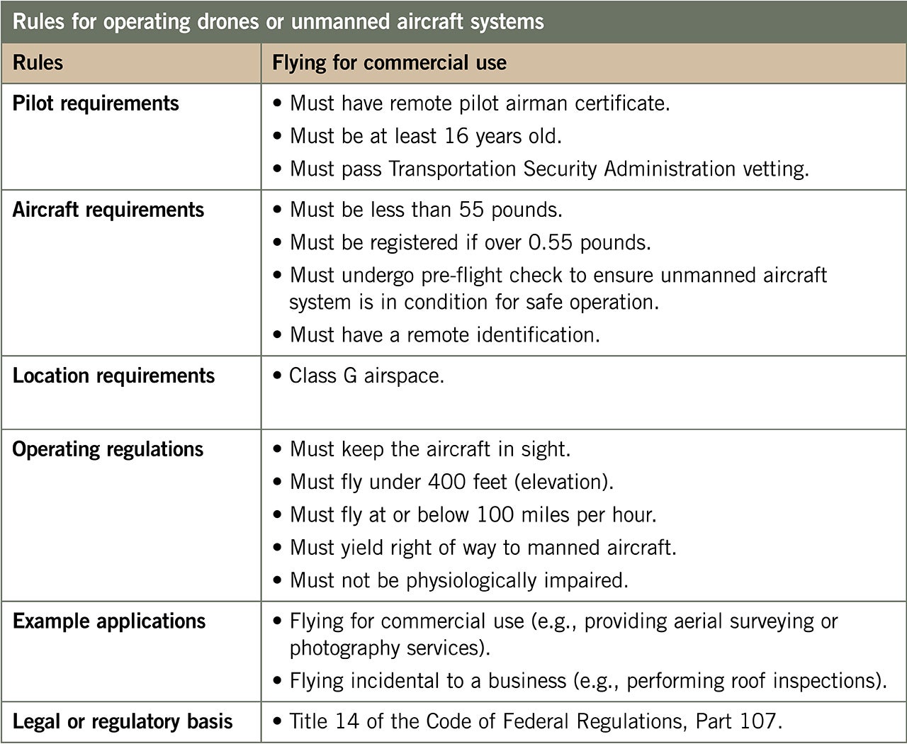
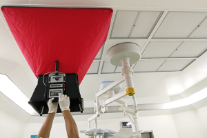
Evaluating a building enclosure using drone or UAS technology
Images that result from drones or unmanned aircraft systems (UASs) are easy to share and interpret. They provide an overview of the building that is often superior to a report collected by sampling individual data points through manual inspection.
Some drone service providers are also able to stream drone imagery in real time, enabling the facilities manager to assess conditions from the ground by observing the drone operator’s monitor.
Click image to enlarge
The drone can also be deployed very quickly and capture the necessary footage in hard-to-reach places much faster than traditional methods. A typical drone flight can be completed within one to two hours, depending on the size of the building.
The advantages of drone and UAS technology include:
Avoids expensive and traditional access methods.
Reduces inspection costs.
- Requires less downtime for relocation and breakdown than other access methods, such as swing staging, scaffolding or aerial lifts.
- Accesses areas that are difficult to reach, such as steep-sloped or inaccessible roofs and higher building elevations.
- Features highly controllable cameras.
- Provides data that can be immediately downloaded to use in reports.
- Produces high-quality video and images of building enclosure defects
- Locates anomalies through infrared camera technology that can assist in finding potential moisture within roofing materials and potential thermal loss within building enclosures (e.g., roofs, walls and windows).
UASs are also very effective at evaluating buildings and property after a major weather event. They are helpful in quickly assessing damage to facilities and are widely used to assist insurance and utility companies.
The major limitation to UAS technology is regulatory requirements (see table in this sidebar) and weather. Drones should not be operated in stormy, windy or extremely cold weather. The wind speed limit is typically around 20 mph. When operating a drone, the pilot must not operate out of the line of sight of the drone. A professional enclosure consultant and/or engineer should interpret and analyze the collected data.
About this article
This article is part of an exchange agreement between the American Society for Health Care Engineering and the International Facility Management Association, which ran an earlier version in its Facility Management Journal.
Kimberly A. Kilroy, PE, RRC, CDT, is a project manager and Jeffrey M. Ziske, PE, CDT, is a project engineer in Gale Associates Inc.’s building enclosure design and consulting group, headquartered in Rockland, Mass. They can be reached at kak@gainc.com and jmz@gainc.com, respectively.
Related Articles
The facilities manager’s role in reducing healthcare-associated infections
From multidisciplinary communication to establishing safety procedures for construction, remediation and maintenance, facilities teams play a critical hand in reducing patient infections.

AdventHealth expands in Tampa Bay with new patient tower
Expected to open in 2029, the new six-story patient tower at AdventHealth Carrollwood will expand inpatient and surgical services for the rapidly growing area.

2026 Vista Award winner Morristown Medical Center
The winning infrastructure project required an untangling of existing systems to provide durable electrical power.